Cryogenic Wollaston Neutron Prism Device
∗ This project is supported by the NSF and a DOE STTR grant
• Introduction
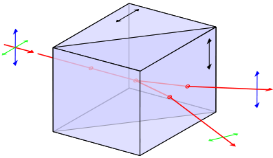 Optical wollaston Prism
Picture from Wikipedia®
Present designs of neutron Wollaston prisms using resistive wire have lower than optimal magnetic fields and place a significant thickness of aluminum wire in the neutron beam. Aimed to solve these problems, in this research project we develop a new design which uses high temperature superconducting tape to carry current and a thin film of superconducting YBCO on sapphire as a Meissner screen.
A prototype prism has been built and tested on the SESAME beam-line at the LENS neutron source at Indiana University and at the HFIR, Oak Ridge National Lab.
• General Device Design
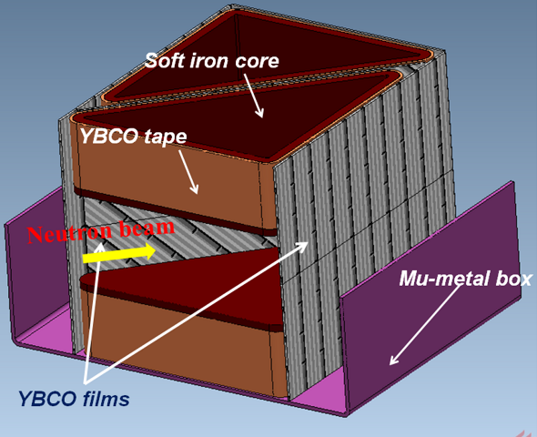
The device uses four, short, triangular solenoids5, each wound with six layers of YBCO super-conducting tape (SuperPower®2G HTS Wire) to generate magnetic fields within the Wollaston prism. In the middle of the Wollaston prism there is an YBCO film (350 nm YBCO foil capped with 100 nm of gold on a 78 x 100 x 0.5 mm sapphire substrate, Theva®, Germany). This film is mounted to provide a well-defined non-adiabatic field transition on a flat surface that is inclined to the average neutron beam direction, as required for SESAME. Two identical YBCO films are installed on the sides of the Wollaston prism that are parallel to the neutron beam to improve magnetic field uniformity. The device is encased in a helium filled aluminum vessel to provide good thermal contact between the cold head of a cryocooler (Cryogenic Refrigeration Systems, Sumitomo® (SHI) Cryogenics of America, Inc.) and the YBCO components.
 Prism Device Configuration
Click to enlarge
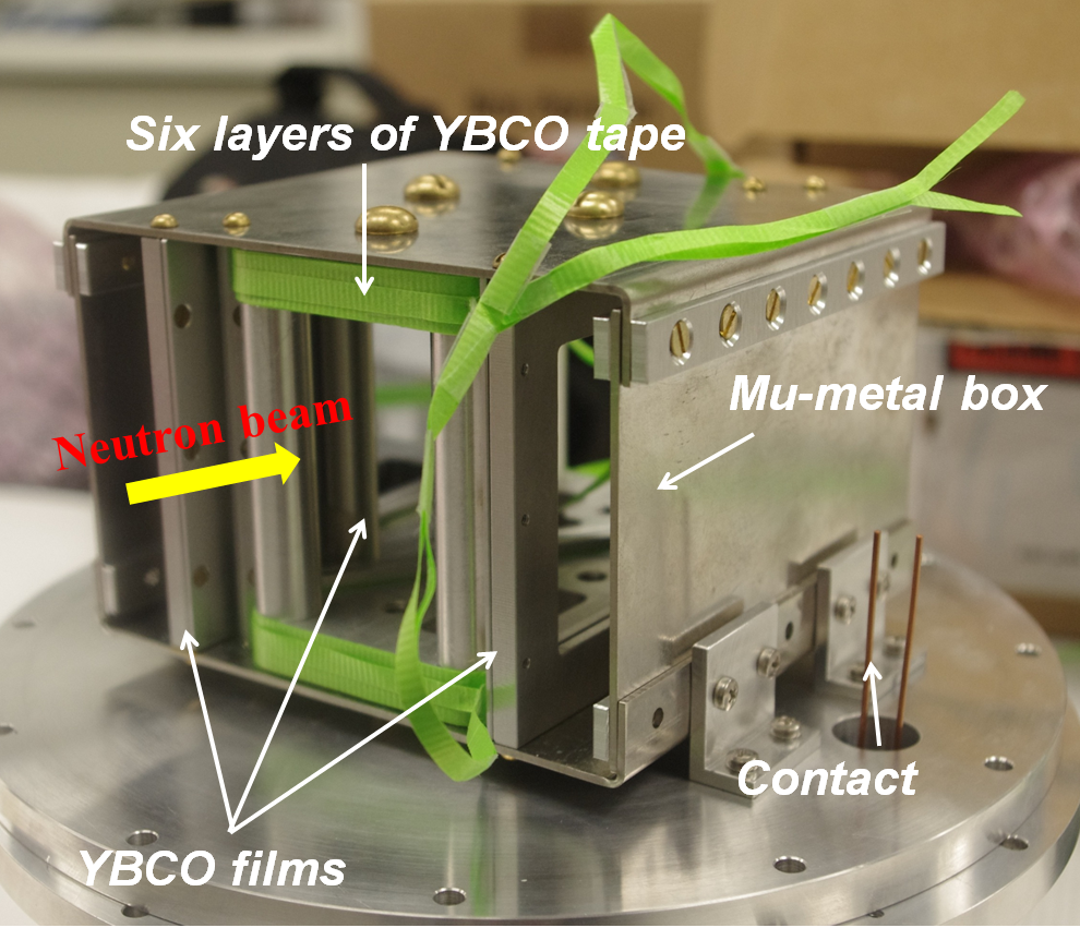 Device Photo
Notice the tape in this picture is not YBCO tape but a test nylon ribbon
Click to enlarge
<< Back to Top
• Preliminary Experiment
To test the function of this cryogenic neutron prism, a Larmor phase measurment test was performed at HFIR, following the same test method described in Ref.1.
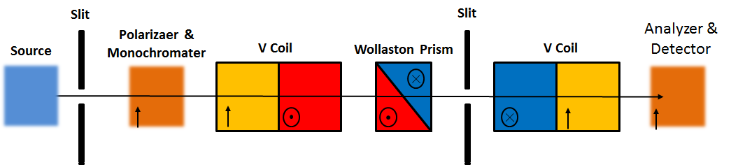
The neutron intensity is measured with the two V-coils acting as a π/2 flippers. In this way, the spin-selected neutron will precess between the two π/2 flipper and its total precession angle depends on its path across the Wollaston Prism. After each measurement, the prism is physically moved transversely to the beam direction. As the Wollaston Prism is symmetric, the precession will be completely cancelled when beam pass along the center line, so the resulting curve of polarization P versus transverse displacement y can be described as:
I(y) = I0+ A·sin[(w·(y-y0)]
Where, I0 is the background intensity with both π/2 flippers turned off, A is the amplitude of sine and w is a constant that depends on the field strength in the prism.
This experiment is performed at CG-1A beamline in High Flux Isotope Reactor(HFIR), ORNL.
• Experiment Picture Gallery
 Complete system mounted
on CG-1A beamline, HFIR
 Heat exchange can
 Front guide field and
monochrometer on CG-1A
 Rear guide field and
 analyzer configuration
• Experiment Data

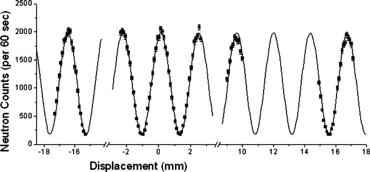
A Preliminary experiment result is shown here:
Upper: Experiment data from HFIR with 8A current through prism coil, 0.5mm step size during transverse movement and 2mm slit size.
Lower: Similar experiment data from non-cryogenic prism[1].
Comparing two experimental results it is obvious that the cryogenic and room temperature device both show sinusoidal behavior. However, the data for the cryogenic device is not a exactly sinusoidal because the field inside prism is not sufficiently uniform
• Field Simulation Result
To better understanding the field configuration inside device and improve future design, we used Magnet© to create a 3D model of future device and simulate the field profile.
 Device 3D model with physics property in Magnet©.
Click to enlarge
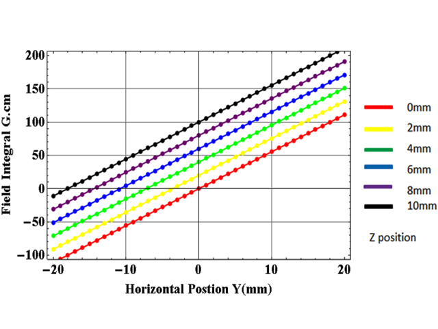 Field integral plot based on simulation result
Each plot is displaced by 10 Gauss.cm for clarity
Click to enlarge
<< Back to Top
• Related References and Resources
• References
1. The use of symmetry to correct Larmor phase aberrations in spin echo scattering angle measurement; R. Pynn, et al; ; Review of Scientific Instruments, 79, 063901, (2008).
2. Spin echo scattering angle measurement at a pulsed neutron sourcet; R.Pynn, et al; Journal of Applied Crystallography, ISSN 0021-8898, (2008).
3. Birefringent neutron prisms for spin echo scattering angle measurement; R. Pynn, et al; Physica B 404, 2582–2584, (2009).
4. The CG1 instrument development test station at the high flux isotope reactor; Lowell Crow, Lee Robertson, Hassina Bilheux, et al; Physics Research A 404, S71–S74, (2011).
• Related Resources
• Poster PDF - Superconducting YBCO Wollaston
prism for Spin Echo Scattering Angle
Measurement (SESAME); F. Li, T. Wang, P. Stonaha, S.R. Parnell, H. Kaiser, D.V. Baxter and R. Pynn; International Collaboration on Advanced Neutron Sources (ICANS XX); Baricloche, Argentina, March 4-9, (2012)
Schematics of Devices and Experiment Details available on request, please contact: Prof. Roger Pynn
<< Back to Top